LED
Hardware setup
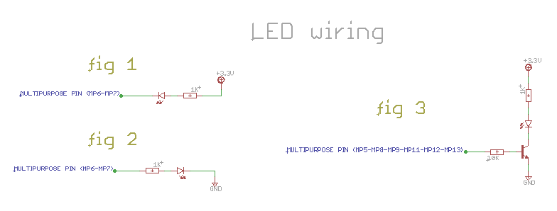
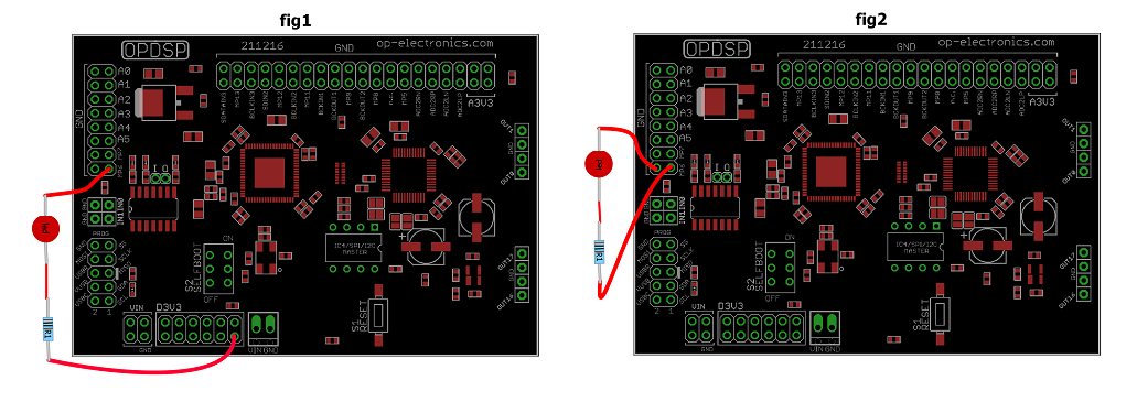
Use MP6 and MP7 for connecting a LED + resistor directly. These pins have inverted logic, when logic HIGH condition in SigmaStudio is sent the pin will go LOW. The easiest way to connect them is like fig1, this way when SigmaStudio sends a logic HIGH level the pin will go LOW and LED will turn on.
You can add one more LED by using the onboard buffer at pins I O close to the 74ACT040 buffer. The “I” stands for buffer input and “O” stands for buffer output. The buffer is of the inverting type. You can route any of MP5-MP8-MP9-MP11-MP12-MP13 to “I” and connect LED+CLR (current limiting resistor) to “O”.
Don’t connect LEDs directly to other pins except MP6 and MP7 or you may damage the board. DSP pins can only supply little current and need a buffer to drive a LED properly.
For additional LEDs you can use an external buffer IC or a simple transistor like fig3.
Fig2 shows an alternative method for connecting a LED.
Software setup
To use a MP pin for driving a LED you must use the following block in the Toolbox path: IO>GPIO>Output:
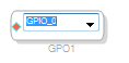
Click on the block, a drop down menu will open where you can select the pin number. For example if you want to use MP6 select GPIO_6
Since MPx pins can be used both as input than output you must set the desired pin as an output for driving the LED.
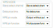
To set pin as an output in SigmaStudio go to Registers Controls tab>MULTIPURPOSE/AUXADC. Find desired pin and set it this way:
MPx pin Mode = Output without pullup
MPx pin function = Multipurpose
For testing that LED works once connected click LINK COMPILE DOWNLOAD (or F7) and click the designed button inside MULTIPURPOSE/AUXADC tab:
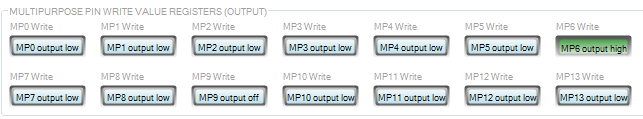
If the LED is connected like in fig1 the LED should turn on as soon as you push MP6 Write button (green indicates the button is pressed)
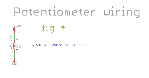
Potentiometers
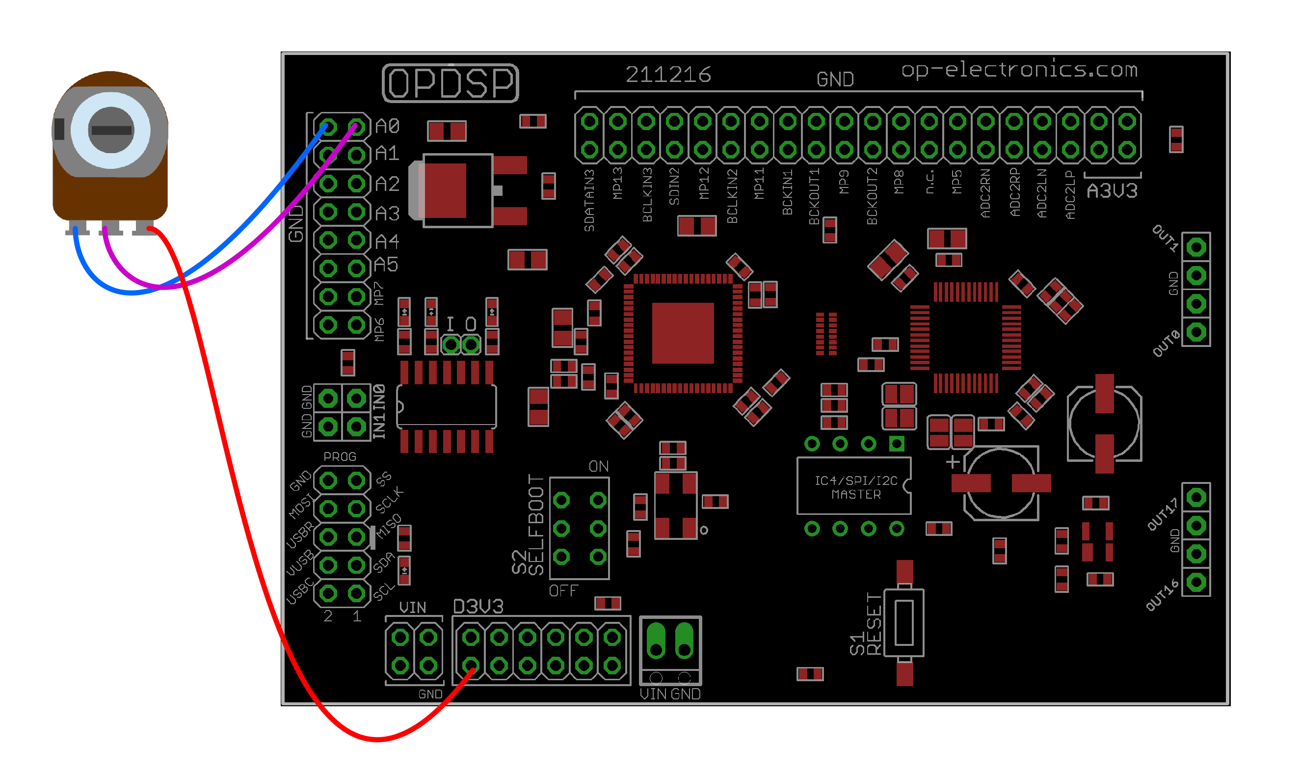
Hardware setup
Software setup
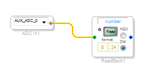
Per testarlo andate nella tab schematic toolbox>IO>GPIO>input e trascinate il Auxiliary ADC input in schematic. Scegliete a quale pin è collegato il pot (A0, A1 ecc), aggiungete DSP Readback che si trova in Basic DSP>DSP Functions allo schema. Collegate i due blocchi e premete il pulsante arancione sul blocco readback. Fatto questo cliccate scaricate il programma sul dsp premendo F7. Nel campo number sul blocco readback noterete dei numeri che vengono aggiornati quando ruotate il potenziometro.
No particular setting is needed to set up AuxADC. To test go to schematic tab: toolbox>IO>GPIO>input and take Auxiliary ADC input into schematic area. Choose the desired pin your pot is connected to (A0, A1 etc), add a DSP Readback, you can find it in Basic DSP> DSP Functions and connect as follows. Click the small blue round button close to “read” (this turns continuous reading on). Now download the algorithm to the DSP with F7. If all is well you can now read data coming from the auxadc as you turn the pot.
Momentary switching
Wiring
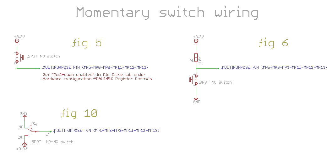
You can wire momentary switches in various ways. One way is like fig5, no external parts are needed and when pushed it sends a HIGH level to DSP. To make it work set the MPx pin as “Pull-down enabled” inside Pin Drive tab. An laternative method for wiring the switch is like fig6, this sends a logic LOW level to the DSP when the switch is pushed.
Software setup
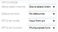
Per entrambi i collegamenti è necessario configurare il multipurpose pin nei registri del dsp all’interno della tab Multipurpose/auxadc come INPUT e multipurpose function:
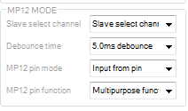
Indipendently how you wire the switch you need to set the pin as INPUT (Input from pin) and Multipurpose function in Multipurpose/auxadc tab:
Per gli switch momentanei c’è un altro parametro da settare che è il debounce time. Dal punto di vista pratico il debounce evita che i rimbalzi all’interno dello switch generino false letture nell’algoritmo in cui lo switch viene utilizzato. Esistono due metodi di debouncing per ADAU1452: software e hardware.
For momentary switches one more parameter needs to be set: debounce time. Debounce time is used to avoid false multiple readings when a momentary switch is pushed. Debounce time value depends on switch type, usually big switch like footswitch needs a longer time while tiny switches like tactile types need shorter debounce time.
You can set debounce time either by hardware or software in SigmaStudio.
For setting hardware debounce go to Multipurpose/auxadc tab:
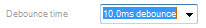
For setting software debounce use the predefined debounce cell:
Number in the debounce cell indicates time as audio samples. To translate in milliseconds use the following formula:
debounce_time(ms) = (1 / frequency_sample)*n*1000
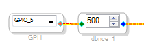
Frequency sample è la frequenza di campionamento (di default 48000) e “n” è il numero di campioni all’interno del blocco. Quindi con frequenza di campionamento a 48000 per avere 10ms di debounce bisogna impostare il blocco a 500.
Frequency sample, as it says, is the sampling frequency set (48000 by default). “n” is number of samples. With n=500 and fs=48000 you get around 10ms debounce time.
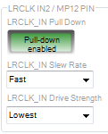
Per il collegamento di fig 5 settare all’interno della tab PIN_DRIVE in Hardware Configuration il pulsante relativo al multipurpose utilizzato come indicato nella figura sottostante:
For fig5 wiring set Pull-Down enabled in PIN_DRIVE tab under Hardware Configuration as follows:
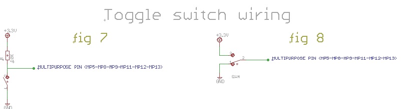
Non-momentary switch
Non-momentary switches can be wired in different ways depending on type. The one in fig7 uses a SPST, when switch is open logic level is HIGH, when closed logic level goes LOW. for SPST fig10 doesn’t use any external part, when switch is closed logic level HIGH is read.
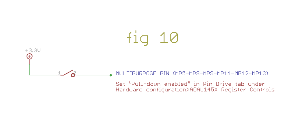
Set the pin as input and multipurpose as well (debounce time is not needed):
For fig10, set Pull-Down enabled in PIN_DRIVE tab under Hardware Configuration as follows:
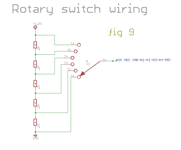
Rotary Switch
Example of a 1P6T rotary switch wiring to AuxADC: