OPUSBi clone
USBi clone controller is made from CY7C68013A module and a shield pcb with some parts which need soldering to the shield pcb.
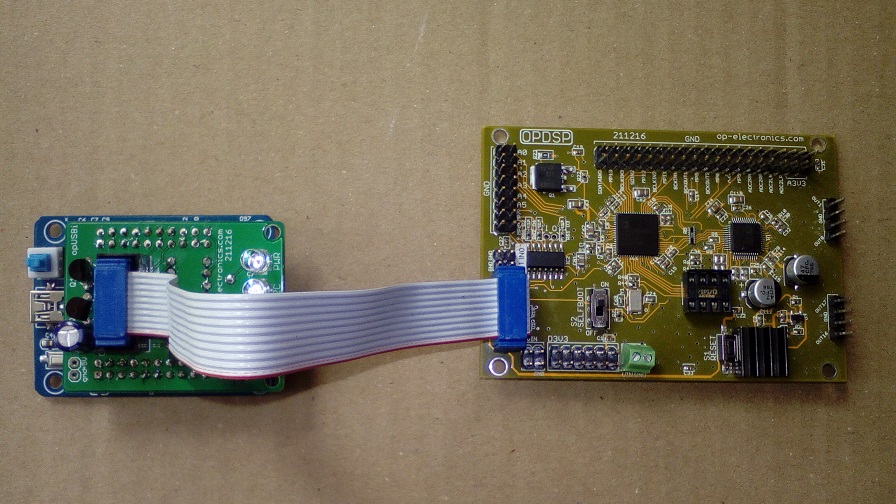
To connect USBi to DSP board a 10-pin ribbon cable with IDC connectors is used. USBi is connected to host PC with mini-USB cable.
Building USBi
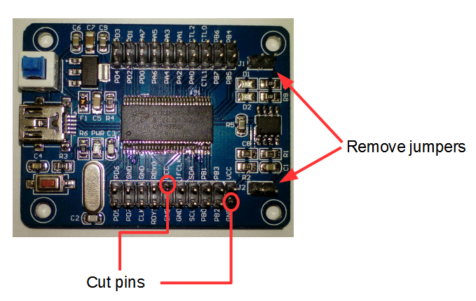
1) Remove J1 and J2 jumpers from CY7C68013A module
2) Cut VCC and GND pins as showed:
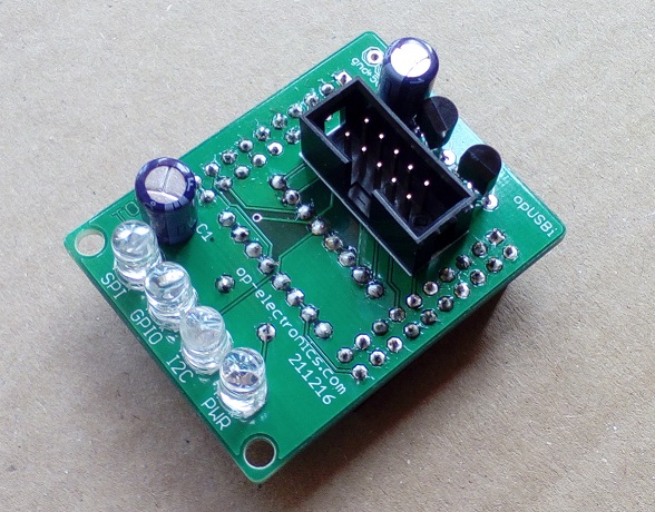
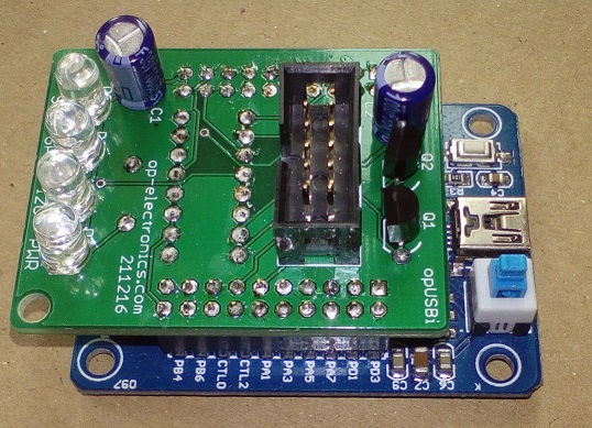
3) Assembly and solder all parts for the shield PCB. This PCB has components both on TOP than BOTTOM sides
TOP side:
– 10-pin male IDC header, D1, D2, D3, D4, Q1, Q2, C1, C2
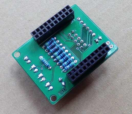
BOTTOM side:
– JP1 and JP3 2×20 female headers, resistors.
4) insert shield board upon CY7C68013A module as showed:
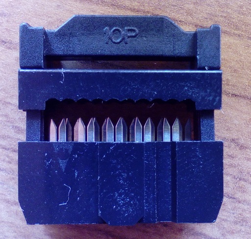
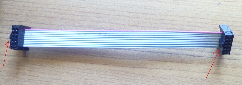
5) wire the 10-pin ribbon cable as showed in the following pics.
Assembly connectors as showed:
Place and align ribbon cable inside connectors as showed:
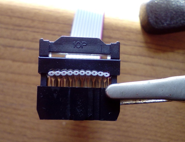
Press down both parts of the connector with adeguate strenght to secure the ribbon:
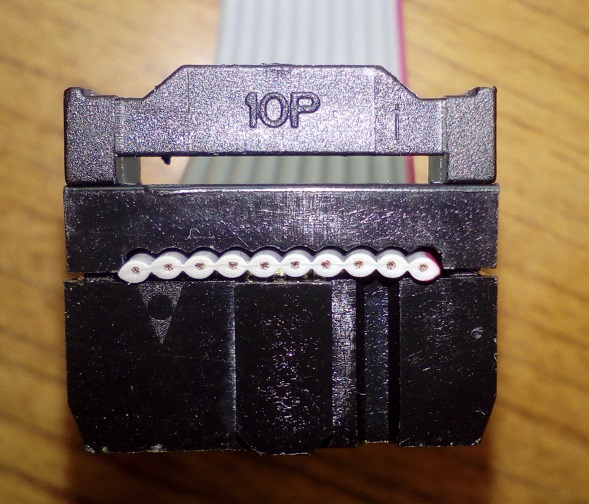
Make sure both arrow indicators are oriented as follows, one external and one internal with respect of the cable:
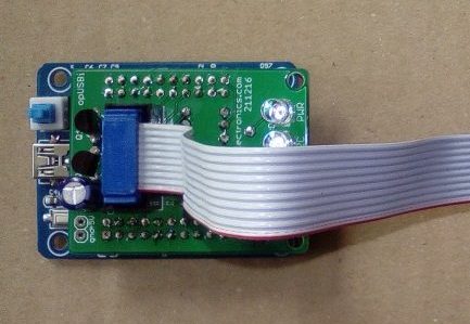
6) Connect ribbon cable to USBi as showed:
USBi BOM
| Qty | Value | Device | Package | Parts | Description |
| 2 | – | PINHD-2X10 | 2X10 | JP1, JP3 | FEMALE HEADER |
| 1 | – | PINHD-2X5 | 2X05 | USBI | MALE HEADER |
| 2 | 100u | CPOL-EUE2.5-6 | E2,5-6 | C1, C2 | POLARIZED CAPACITOR |
| 2 | 10K | R-EU0204/7 | 0204/7 | R3, R4 | RESISTOR |
| 1 | 1M | R-EU0204/7 | 0204/7 | R8 | RESISTOR |
| 2 | 2N7000 | 2N7000 | TO92 | Q1, Q2 | MOSFET |
| 5 | 470R | R-EU0204/7 | 0204/7 | R2, R5, R6, R7, R9 | RESISTOR |
| 1 | 47R | R-EU0204/7 | 0204/7 | R1 | RESISTOR |
| 4 | LED | LED | 5/3mm | D1, D2, D3, D4 | ANY COLOR |
Driver and software installation
Download and install SigmaStudio from the following link
Install USBi drivers from the following link
Test USBi
Connect the USBi controller to a USB port, power it ON with blue onboard switch. PWR LED should turn on.
Start SigmaStudio and create a new project, take USBi block from left column under Communication Channels to the white space area under the tab Hardware Configuration. If block goes green like the following SigmaStudio detected USBi succesfully. If block remains red something is wrong:
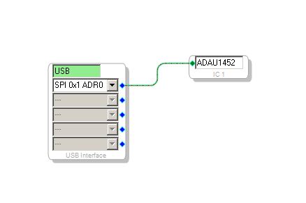
Now take the ADAU1452 block under Processors, connect it to the USBi block as in the above picture and hit F7 or Link Compile Download. Observe the SPI LED, it should turn on and start flashing at high speed meaning data is being transfered.
Connect the ribbon connector to adau1452 board as follows: