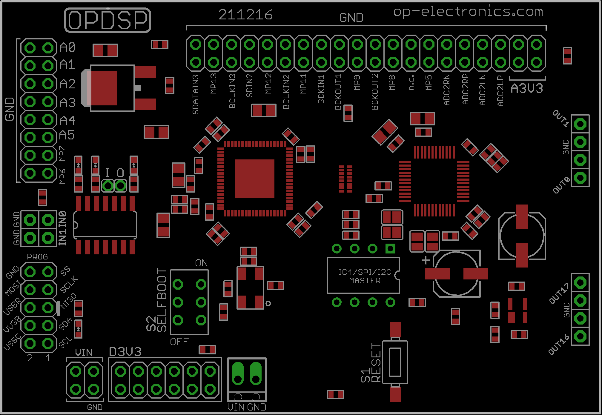
IC4/SPI I2C MASTER
These pads go to adau1452 I2C/SPI master control port. You can solder an eeprom memory like 25aa1024 or headers if you are going to use the board as a shield and you want to add external RAM too.
OUT0, OUT1, OUT16, OUT17 & IN0, IN1
These are 4 analog outputs and 2 analog inputs. Input can accept line level low impedance signals, for hi-Z sources a high input impedance is needed.
Input impedance: 5Kohm
Output impedance: 200ohm
VIN power supply pins
Connect your PSU to any of these pins. Input voltage range is 5V to 12V. Current draw can be in the range of 300 to 500mA depending on DSP peripherals use. The LDO regulator has current limiting and thermal shutdown capabilities but doesn’t offer polarity reverse protection.
PROG connector
This goes to adau1452 SPI slave control port. Connect USBi controller for programming, MCU or your development board. Pay attention that adau1452 pins are NOT 5V tolerant, an external level shifter circuit is needed for connecting to 5V hardware. Solder a 2×5 header connector here.
D3V3
These 3.3V pins can be used as reference voltage for GPIO, AUXADC or to power external hardware
A3V3
Still 3.3V but filtered from digital supply. Useful for powering analog audio circuits.
GND
Lot of ground pads available!
A0-A5
AuxADC inputs for connecting potentiometers and other parts.
MP5-MP6-MP7-MP8-MP9-MP11-MP12-MP13
These pads can be used for GPIO (general purpose input/output functions) like connecting switches, LEDs etc.
MP6 and MP7 are buffered and most likely used to drive LEDs
Never connect LEDs to any GPIO pins other than MP6 and MP7 without a buffer in between.
ADC2RN, ADC2RP, ADC2LP, ADC2LN
Auxiliary audio inputs. External differential driver circuit needed.
Pad I e pad O
These pads are input and output of a 74ACT040 single buffer stage . Buffer is inverting type.
Selfboot switch
When ON the adau1452 is booted from program stored inside eeprom if available.
Reset switch
Pressing RESET switch generates a hardware reset. Can be useful to test if a program has been stored to eeprom.
LEDs
There are 4 LEDs on board:
– Red: indicates 3.3V from regulator is available. If off either LED is burned or there’s a major problem somewhere
– Yellow: turns on when RESET is pressed.
– Green: it’s on when in selfboot mode
– Blue: turns on when USBi is connected